
In this example, the analysis of the two-dimensional subsonic flow over a NACA 0012 airfoil at various angles of attack and operating at a Reynolds number and Mach number 

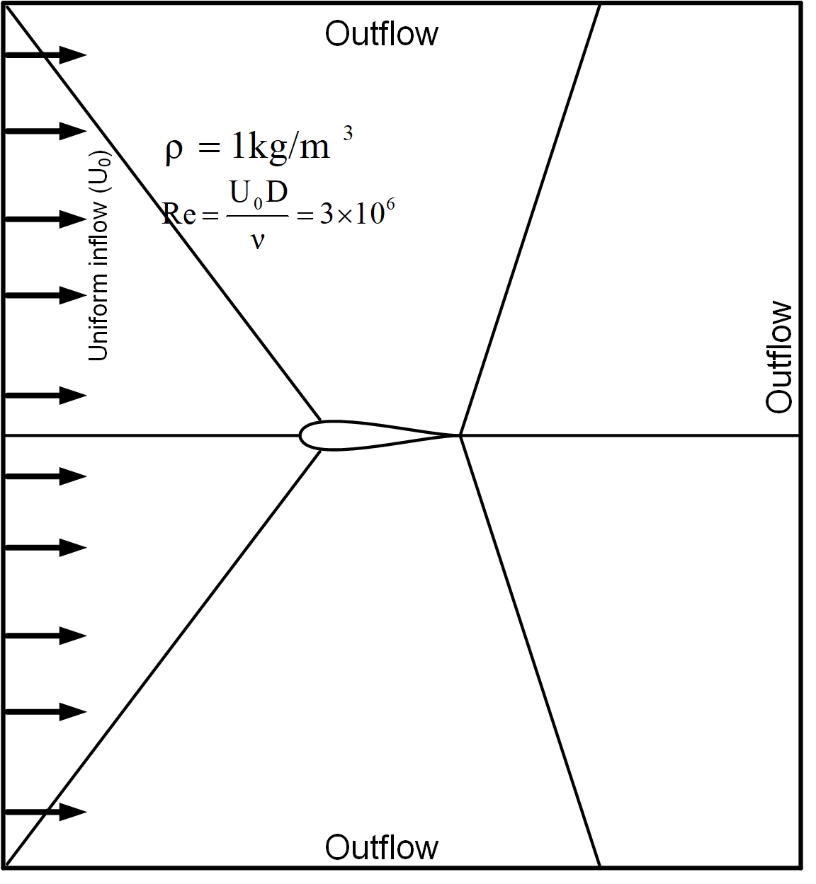
Figure 1: Geometry for turbulent flow over a backward-facing step.
Here are the sections of this post:
- Assumptions
- Case-setup and Boundary Conditions
- Grid convergence study
- Results and Verification
- Conclusion
- Some Useful References
- Future Work
Download the case file here.
Assumptions
- Incompressible flow
- Turbulent flow
- Newtonian flow
- 2-Dimensional flow
- Negligible gravitational effects
- Sea level conditions
- RANS turbulence modeling without wall functions
Case-setup and Boundary Conditions
The flow over NACA 0012 airfoil which is used in wind turbine blade is investigated using OpenFOAM, the steady incompressible solver simpleFoam with the SA model. Pressure and velocity coupling for the Navier-Stokes equation is solved by the SIMPLE algorithm. The convective term is discrete with the upwind scheme. A central scheme is used to discrete diffusion term and gradient term with a second order. Note that the boundary conditions for 

Grid Convergence Study
Three types of grids are generated. For the fine grid, the computational domain was composed of 155608 cells emerged in a structured way, taking care of the refinement of the grid near the airfoil in order to enclose the boundary layer approach. Therefore, sets of y+ less than 1 in order to simulate sub-layer flow in the boundary layer are considered. Calculations were done for constant air velocity altering only the angle of attack for every turbulence model tested. Figure 2 shows a close-up view of the grid system provided for this case.


Figure 2: Coarse, medium and fine grids used for the simulations.
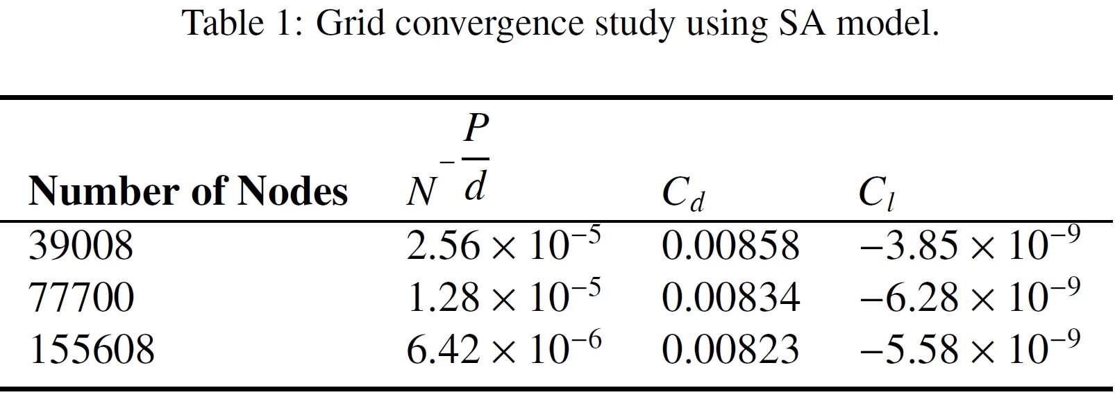
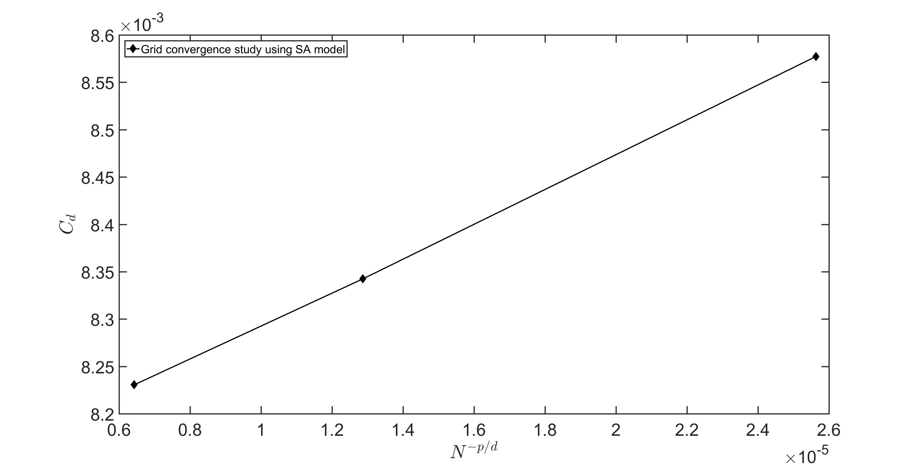
Figure 3: Grid convergence study for the drag coefficient vs. the number of nodes.
Results
Figure 4 illustrates the pressure and velocity distributions over NACA 0012 at zero angle of attack. As expected, the flow is fully symmetric.


As in the current case, a RAS model has been implemented, it is necessary to guarantee that the first node of the mesh falls within the viscous sublayer region. It is to ensure that 
Verification Study
Data for the lift and drag characteristics of the NACA 0012 airfoil were collected utilizing different CFD solvers. This airfoil was chosen because it has been used in many constructions. Typical examples of such use of the airfoil are the B-17 Flying Fortress and Cessna 152, the helicopter Sikorsky S-61 SH-3 Sea King as well as horizontal and vertical axis wind turbines.
The numerical values of lift and drag are given in Table 2, where I have adjoined data from CFL3D to data from the TMR website. Figures 5, 6, and 7 show pressure coefficient Cp over the airfoil surface of the airfoil for the three angles of attacks. The current results using OpenFOAM and CFL3D results are very close to one another.


Figure 5: Pressure coefficient, NACA0012, SA model OpenFOAM vs CFL3D.

Figure 6: Pressure coefficient, NACA0012, SA model OpenFOAM vs CFL3D.

Figure 7: Pressure coefficient, NACA0012, SA model OpenFOAM vs CFL3D.
The lift and drag coefficients are in very good agreement with other CFD solver results.
Conclusion
In this example, I showed the behavior of the 4-digit symmetric airfoil NACA 0012 at various angles of attack using the SA model. The predicted lift and drag coefficients were in good agreement with other CFD solver.
Some Useful References
- Eleni, Douvi C., Tsavalos I. Athanasios, and Margaris P. Dionissios. “Evaluation of the turbulence models for the simulation of the flow over a National Advisory Committee for Aeronautics (NACA) 0012 airfoil.” Journal of Mechanical Engineering Research 4.3 (2012): 100-111.
- Ahmed, Tousif, et al. “Computational study of flow around a NACA 0012 wing flapped at different flap angles with varying mach numbers.” Global Journal of Research In Engineering(2014).
- https://turbmodels.larc.nasa.gov/NAS_Technical_Report_NAS-2016-01.pdf
- Anderson Jr, John David. Fundamentals of aerodynamics. Tata McGraw-Hill Education, 2010.
- Excel datasheet for the pressure coefficient distribution.
Future Work
- I will be considering
SST model for future verification.
- I will be using the same mesh strategy on a vertical axis wind turbine to optimize both the pitch angle as well as the airfoil geometry.
