Flow Over a Flat Plate

Laminar Flow Over A Circular Cylinder

A common practice to verify and validate the OpenFOAM solver is the laminar two-dimensional flow around a cylinder. In this example, I will solve this problem using the simpleFOAM solver, which a steady state for incompressible Newtonian fluids. To begin, consider the two-dimensional flow around a cylinder with radius R_{cyl}= 0.5m. The far-field boundary at a radius of R_{max}= 10m.

problem2

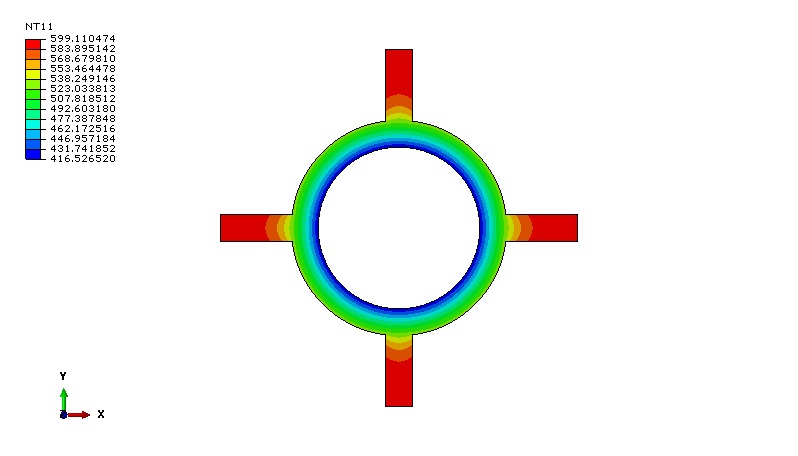
Figure 1: Problem Description.

Using the given incoming velocity V= 1m/s, density \rho= 1kg/m^3, as well as the dynamic viscosity of \mu= 0.025N.s/m^2, one can calculate the Reynolds as follows;

Re= \dfrac{\rho U_{\infty} 2R_{cyl}}{\mu}=40

Here are the sections of this post:

  1. Assumptions
  2. Case-setup and grid Generations
  3. Drag Calculations
  4. Grid convergence study
  5. Validation
  6. Conclusion

Download the case file here: Laminar-Flow-over-a-cylinder

Assumptions

  • Incompressible flow
  • Laminar flow
  • Newtonian flow
  • 2-Dimensional flow
  • Negligible gravitational effects
  • Sea level conditions

Case setup and Grid Generations

Again, the purpose of this test is to verify and validate simpleFoam’s ability to predict the flow structure against the experimental result. The present calculation was confined to the low-Reynolds-number regime Re=40, which encompasses steady symmetrical separated.

The no-slip wall condition is applied to the cylinder wall. Uniform free stream conditions are applied at the inlet and outlet boundaries.

BC

Figure 2: Quadrilateral mesh.

Drag Calculations

The drag force coefficient C_{d} of the cylinder is determined using the force function in OpenFOAM. The force function calculates the forces and moments by integrating the pressure and skin-friction forces over a given list of patches, and the resistance from porous zones. Then the drag coefficient C_{d} is calculated by summing both forces on specified patches and normalize it to the dynamic free-stream pressure as in the following two equations;
F = F_{pressure}+F_{Viscous}=\oint \left( p-p_{ref}\right)dA + \oint \mu\dfrac{du}{d\overrightarrow {n}} dA
\vec{F_{d}} = \vec{F}_{pressure}+\vec{F}_{viscous}=\sum_{i} \rho_{i} \vec{s}_{f,i} \left(p_i - p_{ref}\right)+\sum_{i} \vec{s}_{f,i} \cdot \left(\mu R_{\mathrm{dev}} \right)
C_{d} = \dfrac{F_{d}}{0.5\rho U_{\infty}^2 A_{cyl}}
where p_{i} 
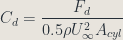
is the local pressure at the wall surface, p_{ref} is the reference pressure used to reduce round-off error during the computation of pressure force, \mu denotes the dynamic viscosity of air, R_{\mathrm{dev}} represents the velocity gradient at the wall surface. Furthermore, U_{\infty} is the incoming velocity and A_{cyl} is the area of the cylinder section.

Grid convergence study

All grids were generated using the open source software Gmsh. Three different resolutions figure (3) were made of the same family of meshing with spacing 0.05, 0.01, and 0.008 respectively. Based on the selected grids, simpleFOAM was run on each grid to obtain the value in which I decided to make my study. In this case, I chose the drag coefficient for each grid resolution table 1 and figure 4.

This slideshow requires JavaScript.

Figure 3: Shows coarse, medium, and fine mesh grids.

CdvsNCyl

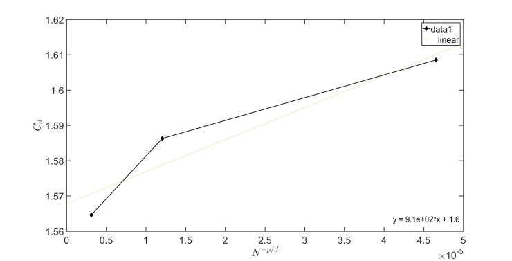
Figure 4: Grid convergence for the flow over a cylinder.

Since the simpleFOAM is a second order accurate, hence, P in table 1 is the effective order of convergence, and d is the number of spatial dimensions. Therefore, P=2 and d=2. Hence, performing a Richardson extrapolation, and calculating the grid convergence index to ensure that you are in the asymptotic range of convergence. This can also be noted in table 1.

CGS

It should be noted from table 1 the pressure force is the dominant part i.e. pressure force = 0.51 in compared to viscous force=0.27. This indicates that most of the drag comes from the pressure force since pressure force comes from the eddying motions that are set up in the fluid by the passage of the body. While viscous force is important for attached flows (that is, there is no separation), and it is related to the surface area exposed to the flow, pressure force is important for separated flows, and it is related to the cross-sectional area of the body.

Results

Figure (5) shows one of the histories of convergence obtained during the simulations.

History of Convergenve

Figure 5:  Shows an example of the convergence history for the flow over a cylinder.

Drag Coefficent

Figure 6: Shows the drag coefficient distributions vs. the number of iterations.


Figure 7: Shows the pressure and velocity distributions respectively for the three grids.

Validation

What is the predicted drag coefficient C_{d} at this Reynolds number? Well, from experiments at this Reynolds number the approximated drag coefficient is approximately 1.65. From table 1, simpleFOAM predicted C_{d}=1.602.

Conclusion

simpleFOAM has been validated for a classic example of external flows around a cylinder. The experimental data of the drag coefficient for Re=40 fairly agree well with the CFD data.

Some Useful References

  1. Coutanceau, M. and Defaye, J.R., Circular Cylinder Wake Configurations – A Flow Visualization Survey, Mech. Rev., 44(6), June 1991.
  2. http://www.calpoly.edu/~kshollen/ME554/Labs/validation_example.pdf.

Ph.D.

University of Dayton

dayton_flyers_logo_full

Graduate Research Assistant

Ph.D. Dissertation Title: Analysis and Optimization of Shrouded Horizontal Axis Wind Turbines

So-called wind-lens turbines offer the potential for improved energy efficiency and better suitability for urban and suburban environments compared to unshrouded or bare wind turbines. Wind-lenses, which are typically comprised of a diffuser shroud equipped with a flange, can enhance the wind velocity at the rotor plane due to the generation of a lower back pressure. This work comprises of two main studies which aim to develop fast and accurate simulation tools for the performance prediction and design of shrouded horizontal axis wind turbines. In the first study, I developed a low-order theoretical model of ducted turbines to establish a better understanding of the basic aerodynamics of shrouded wind turbines. Then a cost-effective CFD tool coupled with a multi-objective genetic algorithm is developed and employed to improve the performance of shrouded wind turbines.
IntroFigure2
Figure 1: Wind lens turbine.

Although Low-order theories lack details, it can potentially provide considerable insight into the behavior of complex systems such as ducted wind turbines. In this part of the research study, I focused on developing a one-dimensional analysis of the flow over nozzle and diffuser augmented wind turbines (NDAWT), which was mainly based on the three governing equations and assumptions;

Governing Equations:
❶ Conservation of Mass
\underbrace{\dfrac{\partial}{\partial t} \int_{CV} \rho d\forall}_\text{=0(5)}+\int_{CS} \rho \vec{V}\cdot d\vec{A}=0
❷ Conservation of Momentum
\underbrace{\dfrac{\partial}{\partial t} \int_{CV} \vec{V} \rho d\forall}_\text{=0(5)}+\int_{CS} \vec{V} \rho \vec{V}\cdot d\vec{A}=\vec{F}_{s}+\underbrace{\vec{F}_{B}}_\text{=0(7)}
❸ 1st Law of Thermodynamics
\underbrace{\dot{Q}}_\text{=0(8)}-\underbrace{\dot{W}_{s}-\dot{W}_{shear}-\dot{W}_{other}}_\text{=0(8)}= \underbrace{\dfrac{\partial}{\partial t} \int_{CV} e \rho d\forall}_\text{=0(5)}+\int_{CS} \left( u+pv+\dfrac{V^{2}}{2}+gz\right)  \rho\vec{V}\cdot d\vec{A}
Assumptions:
❶ The turbine is represented as an actuator disc.
❷ The disc is considered ideal (frictionless).
❸ There is no rotational velocity component in the wake.
❹ The entire process is assumed to occur at a small Mach number, and the air density is thus constant (Incompressible flow).
❺ The flow is assumed to be steady.
❻ There are no external forces acting on the fluid up or downstream of the turbine.
❼ Body forces are negligible.
\dot{Q}, \dot{W_{s}}, \dot{W_{shear}}, \dot{W_{other}}=0.

This slideshow requires JavaScript.

Figure 2: Verification and validation study of the 1d model.

I have found that the power enhancement is proportional to the mass stream rise produced by the wind lens or NDAWT, and it can only be accomplished through two essential principles: increase in the area ratios and/or by reducing the negative back pressure at the exit. The thrust coefficient for optimal power production of a conventional bare wind turbine is known to be 8/9, whereas the theoretical analysis of the NDAWT predicts an ideal thrust coefficient either lower or higher than 8/9 depending on the back-pressure coefficient that the shrouded turbine operates at. Then a verification and validation studies were carried out and found a good agreement with both numerical and experimental results. Even though the developed 1-d model lacks details, I have found it to be useful and very well suited for the preliminary design of a shrouded wind turbine where typically a lot of trade-off studies need to be conducted inexpensively. Finally, this work led to a great journal paper with Energies, and it can be found “Theoretical Analysis of Shrouded Horizontal Axis Wind Turbines”.

The second part of the research was mainly on developing a higher fidelity model to be able to predict the power productivity of wind lens turbines in more detailed physics. Not only the power production, but also thrust, and drag coefficients were also of interest. This was established by solving the Reynolds-averaged Navier-Stokes (RANS) equations utilizing the open-source software simpleFOAM (part of OpenFOAM) as a solver and Gmsh as a meshing tool. I began by studying the simpleFOAM solver, which is a steady-state solver for incompressible Newtonian fluids, see figure (3) for the roadmap. This step required setting up the appropriate boundary and initial conditions and utilizing the open-source mesh generator GMSH as well to generate high-quality structured 2D and 3D computational meshes see figure (4). This also followed by inspecting the influence of turbulence models such as k-\epsilon, k-\omegaSST, and Spalart-Allmaras on the flow through and around ducted turbines. Then verification and validation studies were considered, and I found that the k-\epsilon also predicts the experimental results 
1

Figure 3: Roadmap of my Ph.D. work.

Figure 4: Grids generated using Gmsh.

This slideshow requires JavaScript.

Figure 5: Verification and validation of the simpleFOAM solver using different turbulence models.

Upon the verification and validation of the simpleFOAM solver, the implementation of the actuator disk model was achieved by incorporating the blade element momentum body forces into the RANS equations within the simpleFOAM solver to reduce the computational cost of modeling the turbine blades as the equations below.

The incompressible (RANS)  governing flow equations are; 
The continuity equation:
\dfrac{\partial \overline{u}_{i}}{\partial x_{i}}=0
The momentum equation:
\overline{u}_{j} \dfrac{\partial \overline{u}_{i}}{\partial x_{j}}=-\dfrac{1}{\rho} \dfrac{\partial \overline{p}}{\partial x_{i}}+\nu \dfrac{\partial^{2} \overline{u}_{i}}{\partial x_{j}^{2}}-\dfrac{\partial \overline{u_{i}^{'} u_{j}^{'}}}{\partial x_{j}}+\dfrac{\vec{S}_{AD}}{\rho}
Governing Equations for BEM Used with AD Model I
S_{AD_{x}}= \frac{\rho V_{rel}^{2}Bc}{4\pi r t} \left( C_{l}\cos\varphi +C_{d}\sin\varphi \right)
S_{AD_{y}}=  \frac{\rho V_{rel}^{2}Bc}{4\pi r t}\left( C_{l}\sin\varphi -C_{d}\cos\varphi\right)\cos\theta
S_{AD_{z}}=  \frac{\rho V_{rel}^{2}Bc}{4\pi r t} \left( C_{l}\sin\varphi -C_{d}\cos\varphi \right) \sin\theta            
V_{rel}=\sqrt{\left(r\Omega+ v \cos \theta -w\sin\theta \right)^{2}+u^{2}}, ~\space \phi=\tan^{-1} \left( u/V_{rel}\right)
F_{tip}=\dfrac{2}{\pi}\cos^{-1} e^{-f}, f=\dfrac{B}{2}\dfrac{R-r}{R\sin\varphi}
F_{hub}=\dfrac{2}{\pi}\cos^{-1} e^{-f}, f=\dfrac{B}{2}\dfrac{r-r_{hub}}{r_{hub}\sin\varphi}
ImplementationMAP

Figure 6: The implementation of the blade element body forces into the simpleFOAM solver called simpleADFOAM.

This slideshow requires JavaScript.

Figure 7: The pressure and velocity distribution over a wind turbine using simpleADFOAM.

This model allows for realistic rotor data for the sectional lift and drag coefficients for all angles of attacks via look-up tables. Grid convergence studies for verification and comparisons with experiments for validation are carried out to demonstrate that the adopted methodology is able to accurately predict the performance of a wind-lens prior to performing shape optimizations.

Further investigation also considered on the effect of the turbulence models on the main flow for the case of the lens with and without the turbine as illustrated in figure 8. Figure 9 shows a verification and validation study of the Cii type wind lens using k-\epsilon model. As can be noticed, the current method is in good agreement with experimental results, specifically at tip speed from 3 to 5.5.  

Figure 8:  Streamline distributions for the Cii-type shroud using different turbulent models with and without turbine at a tip speed of \lambda = 3.5.

Cii-1

Figure 9:  Streamline distributions for the Cii-type shroud using different turbulent models with and without turbine at a tip speed of \lambda = 3.5.

Finally, the wind-lens performance is increased by designing the shroud and wind turbine shapes as well as flange height through an optimization process that seeks to maximize the power while minimizing drag and thrust forces. The employed optimizer is a multi-objective genetic algorithm (MOGA) see figure 10. Bezier curves are used to define the chord and twist distribution of the turbine blades and a piece-wise quadratic polynomial is utilized to define the shroud shape. It is demonstrated that the resulting optimal designs yield significant improvements in the output power.

OPNEWFInal1Final

Figure 10: Optimization framework.

ezgif.com-video-to-gif

Figure 11: Example of the MOGA optimizing the twist, chord, and lens shape.

This slideshow requires JavaScript.

Figure 12: Optimized wind lenses.

In summary, 

❶ I utilized open-source mesh generator GMSH to generate high-quality structured 2D and 3D computational meshes.

❷I integrated a blade element momentum model into the Reynolds-averaged Navier-Stokes equations (RANS) and implemented in the open-source CFD software OpenFOAM.

❸I inspected the influence of turbulence models such as k-\epsilon, k-\omegaSST, and Spalart-Allmaras on the flow through and around ducted turbines.

❹ I implemented a shape parameterization based on Bezier curves for the blade twist and chord distribution to attain maximum energy generation, as well as optimization framework to existing flanged wind turbines from the literature to ensure seamless project operations.

❺I established and executed actuator disk model in OpenFOAM in parallel and axisymmetric mode, comparing obtained results to the wind tunnel and numerical test data for verification and validation purposes

❻I successfully developed an analytical 1D model by utilizing elementary governing equations of fluid mechanics to predict the power production of a ducted wind turbine.

❼I designed an optimization framework that couple the multi-objective genetic algorithm implemented within DAKOTA and the actuator disk model in OpenFOAM to improve both the turbine rotor as well as the duct profile.

MEE 312L Graduate Student Instructor

While a doctoral candidate at the University of Dayton, I have enjoyed a diversity of teaching opportunities. As a Graduate Student Instructor (GSI) for the material lab course (MEE312L; 2 semesters), I prepared and delivered experiments including tensile testing, three-point bending test, cold working, and heat treatment for three sections per week. In addition, I also worked with the class (MEE312) instructor to grade the students’ homework assignments as well as a substitute teacher to cover lectures at the absence of the main instructor.

The objectives of the first experiment were to determine the mechanical and physical properties of AA 2011 aluminum and C1018 steel and compare the collected data to matweb for the design of a truck bedI focused on reinforcing core concepts and principles such as the difference between Body Centred Cubic (BCC) vs. Face Centered Cubic (FCC) crystal structures and the main components of stress-strain curves, true and engineering stress-strain, clip-on extensometer, and video extensometer through a 30 min lecture. Then guiding students to do the appropriate measurements (sample preparation) for the tensile testing utilizing the ASTM standard of testing. Upon finishing the experiments and collecting the appropriate data, I guided students to perform data analysis utilizing Excel, verification, and interpret the data for the design of a truck bed.

In the second experiment, I introduced composite material and how we can make it, applications, pros of using composite materials as well as its classifications.  Then I motivated the subject with some real examples through a 20 min lecture. Then 

University of Dayton Department of Mechanical and Aerospace Engineering, Dayton, USA
Facilitated students’ laboratory learning experiences. Experiments included tensile testing, three-point bend testing, and heat treatment. Delivered short lectures, helped students with their reports, graded homework assignments. 

Teaching students have given me a better worldview and helped me realize what’s truly important in life. I am very grateful of the friends and the impact I have made on the material lab.

Key Achievements:

Key Achievements:

❶Tested the mechanical properties for given material and dealt with tensile testing of material, three points bend test of composite materials, heat treatment of copper, steel, and aluminum.

❷Guided students in three classes through daily lab experiments from inception to completion.

Fluid Mechanics – Teaching Assistant 

University of Dayton Department of Mechanical and Aerospace Engineering, Dayton, USA

❶ Held accountability of teaching Fluid mechanics to undergraduate students. Provided assistance in finalizing weekly assignments by clarifying fundamental principles to learners.

❷ Streamlined procedures for grading weekly assignments, quizzes, and midterms to convey feedback and advice regarding the performance of undergraduates.

Computational Method for Design – Teaching Assistant

University of Dayton Department of Mechanical and Aerospace Engineering, Dayton, USA

Enhanced knowledge of undergraduate students by successfully developing an understanding of various lectures including MATLAB within a class.

Key Achievements:

❶ Held responsibility of professor during the absence of lecturer and directed classes to guide students with courses.

Aerodynamics – Teaching Assistant 

University of Dayton Department of Mechanical and Aerospace Engineering, Dayton, USA

Performed duties of teaching Aerodynamics to students. Formulated detailed solutions for all homework assignments for students.

Key Achievements:

❶Ensured every student learns materials taught within a class by conducting weekly office hours.

Aerodynamics-Sample solution 1

Aerodynamics-Sample solution 2

AEE 558 Computational Fluid Dynamics – Third Project (Potential Flow)

This was a project for my CFD class during my Ph.D. journey. It focuses on the implementation of the potential flow solver using the finite difference method. I was given geometrical dimensions of the cylinder, R_{max}=10, R_{cyl}=0.5, U_{\infty}=1, and N_{r}=N_{\infty}=50 and tasked with writing a second-order accurate potential flow solver for the flow around a cylinder using the successive over-relaxation (SOR) as an iterative method and determining the order of convergence by performing a grid convergence study, and plotting the pressure coefficient distribution and compare it with the exact solution. I was also tasked to compare the simpleFOAM solver within OpenFOAM of the same geometrical dimensions by ignoring the dynamic viscosity and verifying the implemented solver with simpleFOAM. This project was done through Matlab analysis, simpleFOAM and hand calculations. This project was influential because it gave me experience in implementing and understand how CFD solver works.

Cyl
O-Type grid.

This report is meant to understand how to implement a finite difference technique as well as iterative solvers such as SOR into a CFD solver.  It also focuses on how to verify the implementation by performing a grid convergence study as well as confirming the order for convergence. The methodology behind this report is such that it is broken down into five parts. The first three parts consist of the governing equations and how to derive the Laplace’s equation analytically. The fourth part was mainly about the finite difference technique to discretize the Laplace’s equation as well as the iterative solver. The last part was about the results and conclusion

All in All, I have gained great respect for those in the academic and in the industrial world who develop CFD codes which incorporate turbulence modeling, heat transfer and even time-accurate solutions which converge in half the time that this simplified inviscid, irrotational, potential flow code does.

Want more? Click here for the full report and Matlab code for this project.

AEE 546 Finite Element Analysis – Final Project

During my Ph.D. journey in UD, I took an advanced finite element analysis class where I studied and focused on the design and analysis of a pipe with fines and retaining ring in the final project. In the first part of the project, I was given geometrical dimensions of the pipe with fines and tasked to determine the temperature distribution as well as stress distribution by excluding and including the thermal part. In the second part of the project, I was tasked to obtain the force required to open the retaining ring. This project was done through Abaqus analysis.

In the first part of the project, I focused on selecting the appropriate element types such as DC2D4 (Thermal problem) and CPS4I (Stress problem), finite element methods followed by performing grid convergence study using six different grids. Then the stress, as well as the thermal problems were run separately to obtain the dominant part in the problem. It was concluded that the thermal has more influence on the pipe with fines, implying that it is the dominant part.

The second of the part of the project was mainly about redesigning the retaining ring, considering a safety factor, different kinds of materials, as well as the cost.  Furthermore,  I was also tasked to come up with a better design that had less stress retaining ring. 

Want more? Below links contain the full report for this project.

FEA-final-project-heat-problem

FEA-final project retaining ring

IT Technician

I have a fiery passion for technology that has burned within me since I received my first laptop (Fujitsu Lifebook) at 15 years old as a gift from my father (mentor and sponsor) in 1999. I can still remember the 13″ screen and the thickness and overall weight of the laptop. This laptop was one of the fastest at the time–a 100mhz Intel Celeron processor with an external floppy disk drive and Windows 1998. It also had 16MB of SDRAM and an 8GB Hard Drive…isn’t it incredible how fast technology grows? I also can still remember the time I upgraded from Windows 1998 to Windows ME or Millennium then to Windows XP.

Because of this long journey, I decided to join the Udit (University of Dayton information technology) when I started working on my Ph.D. research as a part-time job to share my IT experience. Although not mechanical/aerospace engineering related, this work experience I had has been very influential. In fact, there are some parallels to my current research as an aerospace engineering, especially when I assembled the first 24-core machine for parallel computing. Through UDit, I have learned a lot about how to troubleshoot and resolve problems with customers having trouble with either software (such as operating systems, virus removal etc. ) or hardware issues on the spot. I have also gained great experience in maintaining records; tracking, troubleshooting reporting on technology problems. I have also had a great experience with installing, testing, tracking and monitoring a wide range of commercially available software. All in all, I have gained professional experience and valuable life skills during my time at UDit and the experience opened my eyes to other possibilities.